Problem to solve – Overview of Hires. fix
To understand the necessity of a high-resolution fix (commonly known as Hires. fix or hires fix), consider the following example: In both images below, the main characters are set against a backdrop of sunflowers and the sky. Upon closer inspection, it becomes evident that the eyes of these anime characters lack the necessary detail. Given that these images are at a resolution of 512×512, this issue becomes more pronounced when the images are scaled up. In anime, the eyes are often considered the most expressive and vital features, playing a crucial role in bringing each character to life. Therefore, the absence of intricate details in the eyes can significantly diminish the overall impact and expressiveness of the characters. A hires fix can effectively address this problem.


To understand the modifications required for implementing the Hires fix, it’s essential to first review the standard Stable Diffusion workflow as it operates without the Hires enhancement. Steps in this process are defined in the following manner:
- CLIP Encoding: The CLIP model encodes the input prompt into text embeddings.
- Latent Diffusion: The latent diffusion process, involving a UNet and a sampler, begins with random noise. It then progressively denoises this noisy image, guided by the text embeddings, to create a clean but compressed image.
- VAE Decoding: A Variational Autoencoder (VAE) decoder transforms the compressed image into a final image.
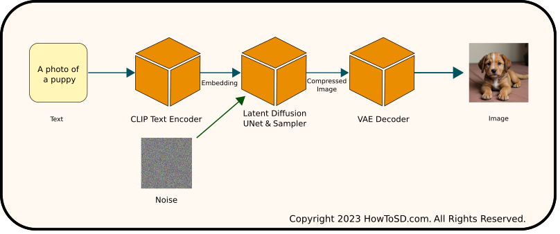
In ComfyUI, the hires fix includes a few additional steps:
- CLIP Encoding: As in the standard process, CLIP encodes the prompt into text embeddings.
- Initial Latent Diffusion: Using the text embeddings as a guide, the process generates a compressed image.
- Scaling: This compressed image is then scaled up.
- Refined Latent Diffusion: A second round of latent diffusion begins, starting with the scaled, compressed image instead of the noise. Again, it uses the same text embeddings to guide the denoising process, ensuring a clean, compressed image with enhanced detail.
- VAE Decoding: Finally, the VAE decoder converts this refined compressed image into the final image.
Additions in the ComfyUI workflow are steps 3 and 4. Note that text embedding generated by CLIP is also fed to the second UNet & sampler. These additional stages introduce more intricate details to the image being generated, significantly improving the overall quality.

Steps to use Hires fix in ComfyUI
Overview
To implement the HiRes fix in your text-to-image generation workflow, as conceptually illustrated in the above diagram, follow these steps. If you haven’t set up a text-to-image flow yet, select Load Default from the main menu to initialize the default workflow.
Here’s how to integrate the Hires fix:
- Insert an Upscale Latent Node
- Add a Second KSampler Node
- Adjust Connections for the Upscale Latent Node
- Adjust Connections for the Second KSampler Node
These steps will modify your existing workflow to incorporate the Hires fix, enhancing the detail and quality of your generated images.
1. Insert an Upscale Latent Node
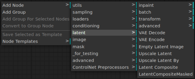
Right-click an open area of ComfyUI and select Add Node | latent | Upscale Latent.
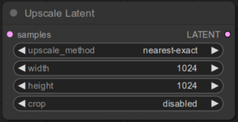
Once the node is added, change width and height to 1024 from 512.
2. Add a Second KSampler Node
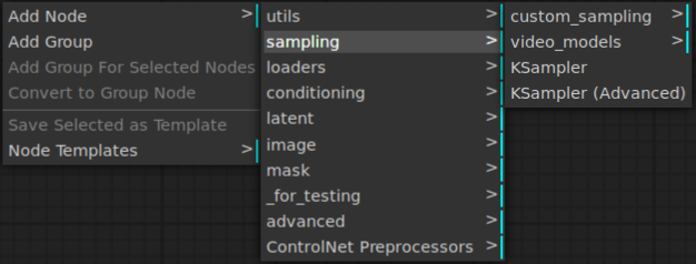
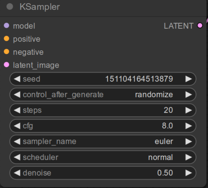
Right-click an open area of ComfyUI and select Add Node | sampling | KSampler.
You should see the node created as shown below. Change denoise to 0.5. This step is very important. You can adjust this value based on the result, but start with this value. We are done with adding required nodes. Let’s move onto adjusting connections.
3. Adjust connection for the Latent Upscale node
Currently LATENT output of the first KSampler node is connected to VAE Decode node. Remove this connection and connect LATENT output of the first KSampler node to samples input of Upscale Latent node.
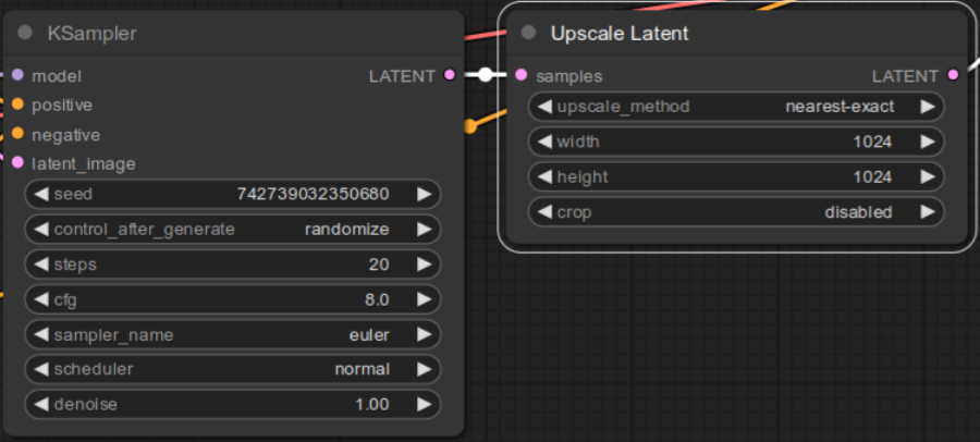
Connect LATENT output of the Upscale Latent node to latent_image input of the second KSampler node.
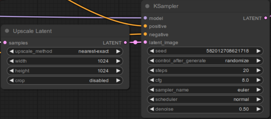
4. Adjust Connections for the Second KSampler Node
To integrate the second KSampler node into your workflow, follow these connection steps. Note that the LoadCheckpoint and CLIP Text Encode nodes should remain connected to the first KSampler node. The connections outlined here are additional, specifically for the second KSampler node:
- MODEL Output to KSampler: Connect the
MODELoutput of the LoadCheckpoint node to themodelinput of the second KSampler. - Positive Prompt Conditioning: Link the
CONDITIONINGoutput of the CLIP Text Encode node (for the positive prompt) to thepositiveinput of the second KSampler. - Negative Prompt Conditioning: Similarly, connect the
CONDITIONINGoutput of the CLIP Text Encode node (for the negative prompt) to thenegativeinput of the second KSampler. - Latent to VAE Decode: Finally, connect the
LATENToutput of the second KSampler to thesamplesinput of the VAE Decode node.
These steps will ensure that both KSampler nodes are correctly integrated into your workflow, maintaining existing connections while adding the necessary ones for the high-resolution enhancement.
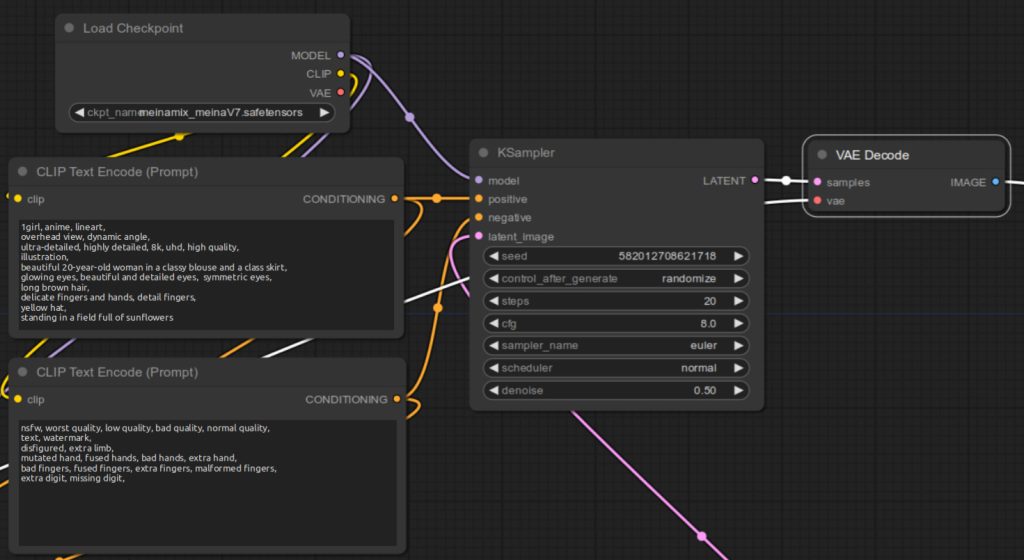
Congratulations on completing the setup! Now that all the wiring is in place, you’re ready to see the results. Simply click on Queue Prompt to generate an image. Below, you’ll find a few examples created using this workflow.
Please note that the fonts in the below diagram are quite small, making it impossible to read the node names and input/output field names. For clarity on these details, refer back to the figures provided earlier.
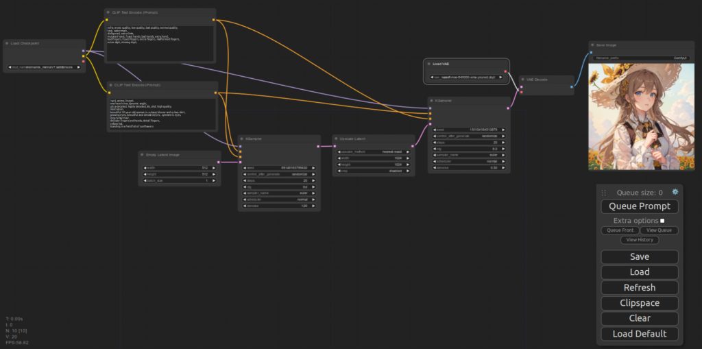
Sample images generated using this workflow


References
[1] comfyanonymous. hiresfix_latent_workflow.png. Retrieved from https://github.com/comfyanonymous/ComfyUI_examples/blob/master/2_pass_txt2img/hiresfix_latent_workflow.png
